HVAC Energy Recovery Wheels
 Introduction
Some facilities have always ventilated large amounts of indoor air. Other facilities may have only recently increased the volume of ventilation air to meet newer building codes requiring more fresh air. Regardless of the reason, dumping conditioned indoor air and replacing it with outdoor air represents energy cost, both in moving the air (fan energy) and in heating, cooling, humidifying or dehumidifying the air. Air to air heat exchangers have been around for many years. They transfer heat only. A newer concept, called enthalpy wheels or exchangers allow both temperature AND moisture to be exchanged. Because the cost to remove moisture can represent 30 to 50% of the cost to condition air, substantial additional savings are available with enthalpy wheels over conventional air-to-air exchangers. Enthalpy wheels do not drop relative humidity as low as is possible with traditional desiccant systems. If the objective is very dry air, then the desiccant system has the advantage. If the objective is primarily heat recovery with a little added boost from also removing some of the moisture, then the enthalpy wheel has an advantage. See also Desiccant Dehumidification
Operation

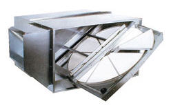
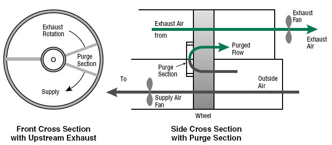
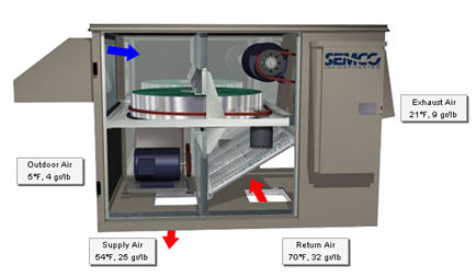
 A wheel coated with a desiccant material or ‘ion exchange resin’ is rotated between the incoming fresh air and the exhaust air. Heat and moisture are given up to the wheel. When the space is in the heating mode, the heat and desirable humidity is used to pre-condition the incoming, cold, dry air. In the cooling mode, the incoming air is pre-cooled and slightly dehumidified. The differences between enthalpy and desiccant wheels include: enthalpy wheels are designed for maximum exchanged of sensible heat and desiccant wheels are designed for maximum exchange of humidity (latent heat). This affects the type and quantity of adsorbent materials used to coat the wheels. Enthalpy wheels are typically easier to clean and require more frequent cleaning because they handle more total air flow. Enthalpy wheels rotate faster, up to 25 rpm, and desiccant wheels rotate only a few times per hour. Desiccant wheels have a ‘reactivation air stream’ to dry the desiccant which allows it to adsorb more moisture when in the wet air stream. Enthalpy wheels require the exhaust and inlet air source to be at the same location. Desiccant systems need only a supply of air from either the outside or inside that is to be dried. A common stated ‘disadvantage’ of enthalpy wheels is that the two air streams can come into contact with each other. The following excerpts from manufacturer’s web sites explain why this is really not a problem. From the AirXchanger web site: Moisture Transfer and Fungal Growth in Desiccant Based Enthalpy Wheels There is evidence that fungi germinate when water condenses onto surfaces of air handling systems where nutrients are present. Surfaces which remain wet for a period of 12 to 24 hours allow fungi and mold spores already present to “bloom”, resulting in a potential IAQ problem. This knowledge has led to questions of whether desiccant energy recovery ventilation wheels, which in fact transfer water from one airstream to another, could provide a medium for growth of mold and fungi. Such is not the case for Airxchange technology, nor has it been reported in the literature for other enthalpy wheels. In silica gel based desiccant wheels, the water molecules are transferred by sorption, individually, onto and off of the silica gel surface. Water is present on the wheel in a molecular layer only. Condensation does not occur. Airxchange desiccant wheels experience “dry” moisture transfer in that there is no bulk liquid water present which could support fungal growth or dissolve other chemical species. The transfer of water onto and off of the wheel’s desiccant surfaces occurs in the vapor or gas phase. There are no “wet” surfaces and liquid water does not enter the airstream. The sensible (non-desiccant coated) wheel can also transfer water through the different mechanism of condensation and re-evaporation, however; again, there is no accumulation of water, unless the frosting threshold is violated through misapplication of the component. In this case, the water is in the form of frost or ice which does not support fungal growth. Sensible (uncoated) wheels from all manufacturers are identical in this regard. Both moisture and nutrients are required to support fungal growth. Therefore dirt accumulation on heat wheels is of potential concern. It is also true that any heat wheel can accumulate semi-volatile compounds like tars and grease which are deposited on surfaces. These surfaces can then become odor and contaminant sources, in the same way that a filter or any other element of an air handling system can become a source of compounds accumulated over time. The Airxchange wheel was designed to respond to these issues over the life of the system by providing for cleaning and maintenance with washable desiccant surfaces, removable segments and easy to access cassettes. Many aspects of this technology are patented and are unique in the industry. From the SG America web site: The innovative Hi-Panex product line of Sensible and Enthalpy wheels, represent the latest development in rotary wheel heat exchanger technology for ventilation air. Seibu Giken developed the use of ion exchange resins in place of traditional desiccants, resulting in the lowest co-adsorption in the industry. Ion exchange resins attract water molecules from air without adsorbing them into pores. This ionic attraction is highest for water due to the polar electrical field of the water molecule. Co-adsorption of non-water vapors is lower than silica gel, lower than 4A and even 3A molecular sieve desiccants. From the EPA Paper ”Laboratories for the 21st Century – DOE/GO-102003-1774 October 2003″ The type of desiccant used in a total energy wheel must be designed to transfer only moisture and not airborne contaminants. To further reduce potential contamination of the supply air stream, the wheel is flushed with supply air that is deflected by a damper in the purging section of the rotor. The damper redirects supply air leaving the wheel to the inlet side of the wheel exhaust. The purge section utilizes the pressure difference between the supply air and exhaust air streams (see Figure above for purge air option). Purge volumes for laboratory applications are typically between 5% and 10%, so additional fan energy is required to move this air.
Savings Potential
The potential savings from an energy recovery enthalpy system is a function of volume of exhaust/replacement air, temperature and humidity differences between the two air streams, and the efficiency of the unit. Enthalpy recovery systems are not inexpensive. For ‘good applications’ payback is generally in the 5 – 10 year range. Of course this also depends on local energy prices. A good starting point is to estimate the amount of ventilation/fresh air make-up that could reasonably be passed through an enthalpy recovery system, and calculate a cost of that air stream. Then, assume that an enthalpy system would reduce that cost by 50 to 80% percent. Equipment and installation costs vary considerably, but if a quick calculation of $5 per CFM results in under a 5 year payback, then it’s worth taking a closer look and get some proposals.
More Information
Desiccant Dehumidification Air to Air Heat Exchangers Ventilation Systems Heat Recovery General The Energy Solutions Center Gas Cooling web site at www.gasairconditioning.org
Manufactures
Airxchange 85 Longwater Drive Rockland, MA 02370 Telephone: 781-871-4816 Web site www.airxchange.com SEMCO, Inc. 1800 East Pointe Drive Columbia, MO 65201-3508 Telephone: 314-443-1481 Web site www.semcoinc.com SG America 5115 Pegasus Court, Suite M Frederick, MD 21704 Telephone: 240-379-7330 Web site www.sgamerica.com See also Desiccant Dehumidification as many manufacturers of desiccant systems also offer a line of enthalpy systems. Source: Text Bob Fegan 1/2009; diagram from EPA paper ‘Laboratories for the 21st Century – DOE/GO-102003-1774 October 2003’; product images from AirXchange web site 9/2005; SEMCO web site 2/2007;
© 2008 Energy Solutions Center400 N. Capitol Street NWWashington, DC 20001 All rights reserved. Legal Contact our webmaster
